Quarter Wave Box Calculator 21

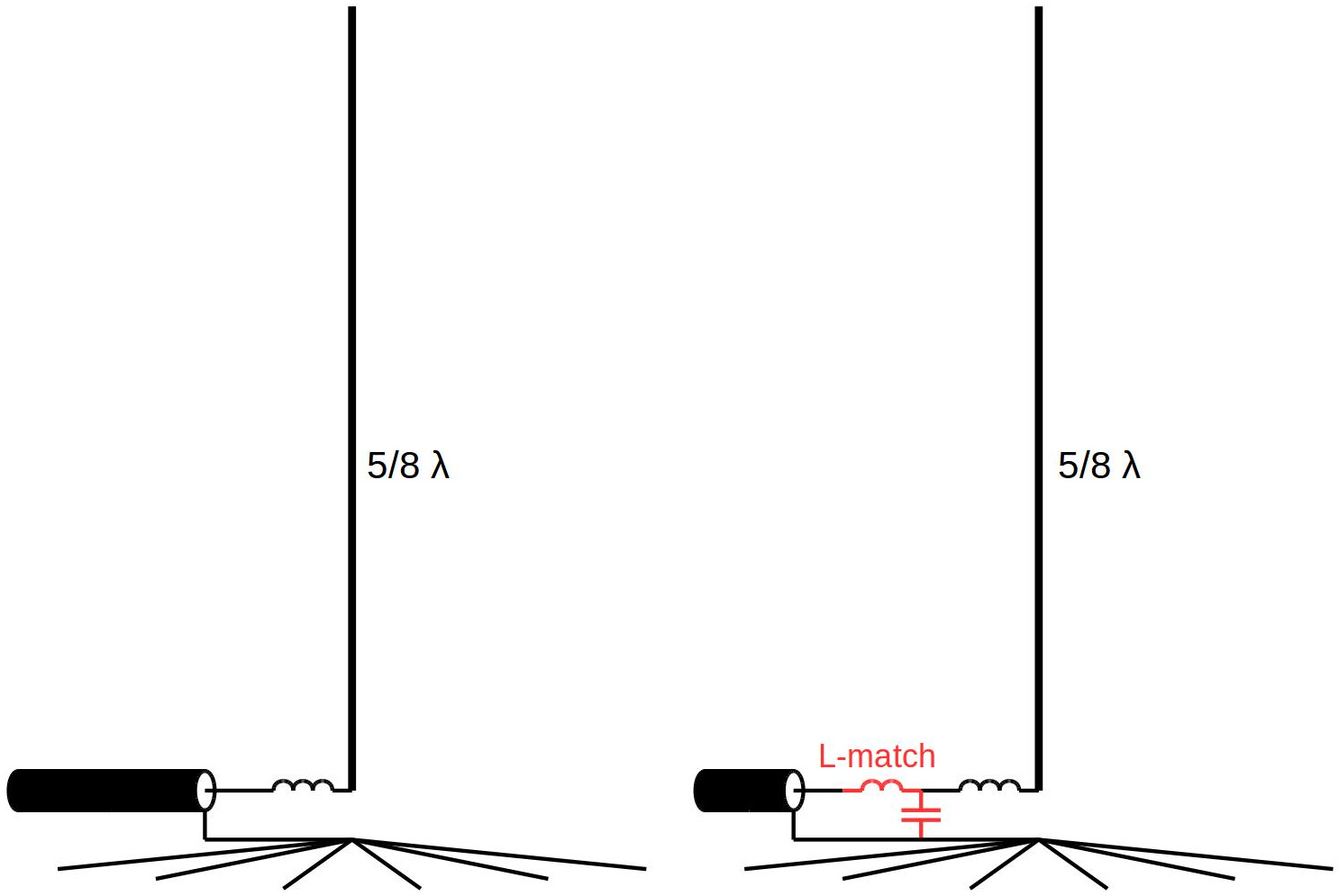
Ahh, the good old quarter wave ground plane! This calculator can be used to design a Quarter Wave Ground Plane antenna, with radials. The radiating element is a quarter wave (λ/4) and the radials are 12% longer. There are usually four radials, three being a minimum, but you could use up to six.
The most common example of a loudspeaker that relies on a quarter wavelength acoustic standing wave is a transmission line enclosure. This style of loudspeaker has been on the fringe of the audio mainstream for many years with just a few smaller companies building and marketing this enclosure.

This is a true unbalanced antenna, with a feed impedance of around 50Ω and therefore a great match to 50Ω unbalanced feedline. The velocity factor is set to 95% which should be fine for most people. You could cut a little on the large side and trim the antenna for best match at your desired frequency if you have the equipment. Kartoteka po svyaznoj rechi. These antennas can easily be built for UHF or above by using a chassis mount N-Type (or SO-239) connector, some solid wire and solder. For VHF and below, as the elements get bigger, some more structured design is needed. A quarter wave monopole mounted against a perfect ground will have an impedance of around 36Ω but by bending the radials down at an angle of 45°, we increase this to around 50Ω whilst at the same time lowering the radiation angle more towards the horizon. (42° is the theoretical perfect angle for 50Ω feed, but who’s measuring!) I have made quite a few of these antennas over the years with good results.
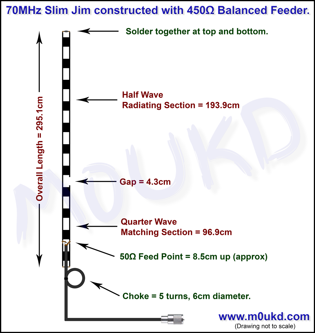
They are very forgiving due to the low impedance feed. I use one at home on 70MHz, to see construction details and more images. The next two images show one I built for the 70cm band. It is good for use between 430-440MHz. It uses 6mm aluminium tube for the radials, 4mm brass tube for the driven element and is built around an N-Type chassis socket mounted to a 40x40mm aluminium square, held together with rivets.
Overview: This is a calculator for designing a 1/4 Wave Flared Vent T-Line/Horn/Bass Reflex Enclosure. The formulas used in the calculator create a design that suggests the most maximally flat response in an anechoic environment based on the number of drivers, the thiele small parameters and the allotted dimensions specified in the user’s input fields. The calculator does NOT take into account the effects of placing the enclosure into the listening environment. This type of enclosure may not be the most suitable option for your application. I recommend reading the articles in the category on box design for further information.
Feel free to check out the other calculators on the site as they may provide the results you are looking for. —> You can also request a totally custom design for your driver(s)/application by filling out the form in the page. The spreadsheet calculator loads via iframe below the diagrams.
- вторник 09 октября
- 69